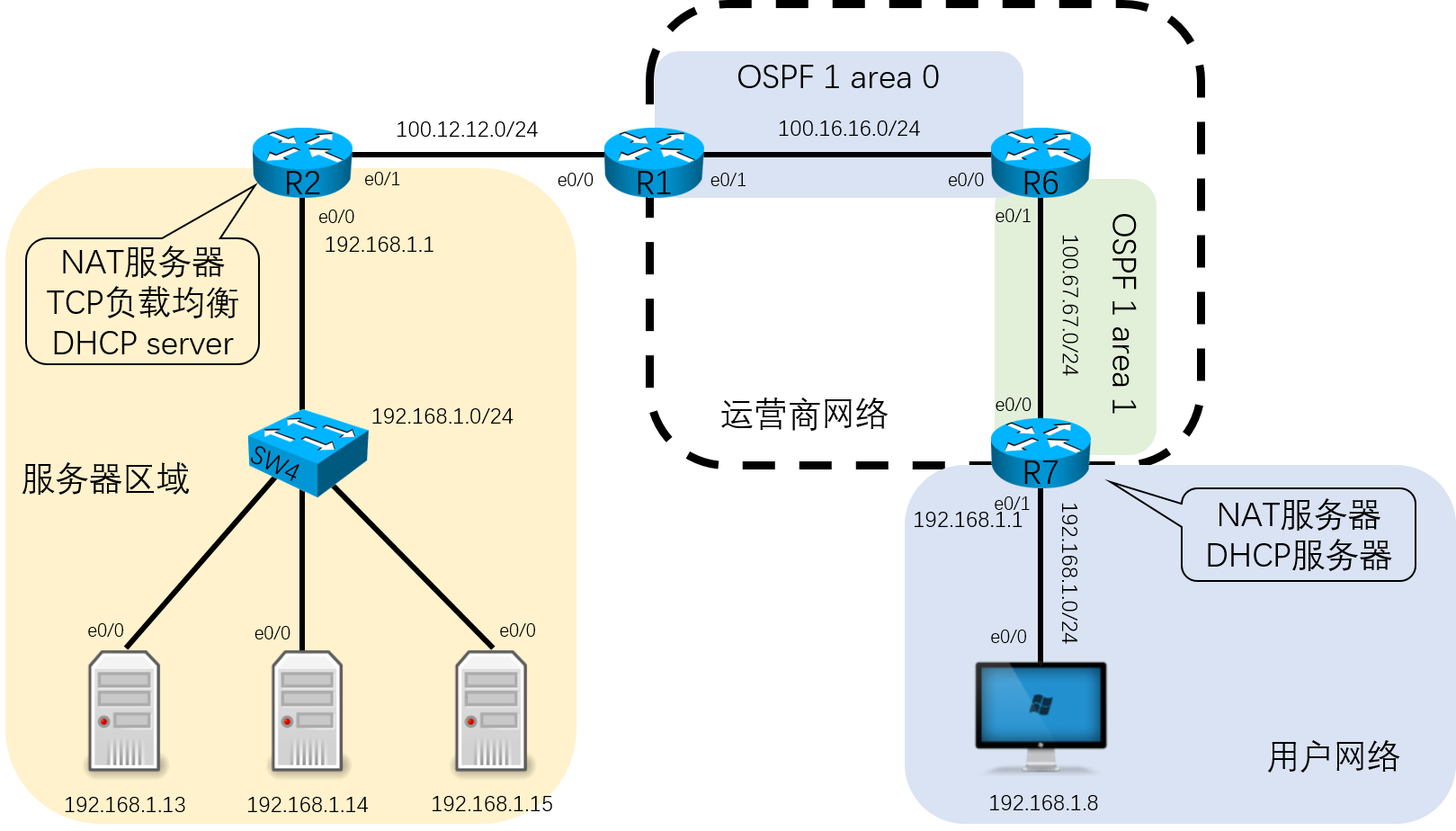
ü 用户网络区域里面R8路由器模拟用户PC,IP地址为DHCP动态分配,要求R7作为用户网络网关,网关地址为192.168.1.1,并且分配固定地址192.168.1.8给PC。
ü R7上做好NAT地址转换,要求PC最终能访问外网(100.x.x.x的网络)。
运营商网络需求
ü 运营商网络要求运行OSPF协议,将物理接口宣告进OSPF。并且R1与R6之间为区域0,R6与R7之间为区域1。最终保障邻居关系的建立,和路由条目的学习。
ü 其中R1的e0/0接口也需要宣告进OSPF,但是R2却不参与OSPF(因为CCNA阶段并没有学习到重分布,此做法并不合适,在CCNP阶段会介绍到。)
服务器区域需求
ü 服务器区域内,R2作为网关设备,在R2上需要配置NAT地址转换,保障服务器可以访问外部网络。
ü R2的e0/0地址为192.168.1.1,并且R2需要充当DHCP服务器,给内部服务器分配IP地址,其中给R3(模拟服务器)固定分配192.168.1.13,R4固定分配192.168.1.14,R5固定分配192.168.1.15。
ü R3、R4和R5上开启telnet服务,作为服务器的发布服务用来测试。
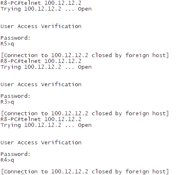
ü 在R2上要求使用NAT做到TCP负载均衡,最终效果可以达到在用户的PC上分多次telnet 100.12.12.2可以返回不同的响应服务器。
基础网络配置
R1
1
2
3
4
5
6
interface Ethernet0/0
 ip address 100.12.12.1 255.255.255.0
 no shutdown
interface Ethernet0/1
 ip address 100.16.16.1 255.255.255.0
 no shutdown
R2
1
2
3
4
5
6
interface Ethernet0/0
 ip address 192.168.1.1 255.255.255.0
 no shutdown
interface Ethernet0/1
 ip address 100.12.12.2 255.255.255.0
 no shutdown
R3&R4&R5&R8
1
2
3
interface Ethernet0/0
 ip address dhcp
 no shutdown
R6
1
2
3
4
5
6
interface Ethernet0/0
 ip address 100.16.16.6 255.255.255.0
 no shutdown
interface Ethernet0/1
 ip address 100.67.67.6 255.255.255.0
 no shutdown
R7
1
2
3
4
5
6
interface Ethernet0/0
 ip address 100.67.67.7 255.255.255.0
 no shutdown
interface Ethernet0/1
 ip address 192.168.1.1 255.255.255.0
 no shutdown
用户网络配置
R7
1
2
3
4
5
6
7
8
9
10
11
NAT地址转换配置
interface Ethernet0/0
ip nat outside
//设置R7的nat的出接口
interface Ethernet0/1
ip nat inside
//设置R7的nat的入接口
access-list 1 permit 192.168.1.0 0.0.0.255
//使用ACL匹配需要地址转换的内网地址
ip nat inside source list 1 interface Ethernet0/0 overload
//配置NAT的地址转换,将ACL 1中匹配的地址,转换为e0/0口的公网地址,而且如果出现多个地址的话,进行地址复用。
DHCP配置
1
2
3
4
5
6
7
8
9
10
11
12
ip dhcp pool cisco
   network 192.168.1.0 255.255.255.0
   default-router 192.168.1.1
//配置ip dhcp 地址池为192.168.1.0 255.255.255.0网段,其中网关地址为192.168.1.1
ip dhcp excluded-address 192.168.1.1
//将网关地址排除在被分配地址之外
show ip dhcp binding
//查看R8的Client-ID,并且复制Client-ID备用
ip dhcp pool bind-8
   host 192.168.1.8 255.255.255.0
   client-identifier <上面复制来的Client-ID>
//配置一个新的DHCP地址池,用来绑定R8分配的地址为192.168.1.8
R8
1
2
3
4
R8-PC(config)#interface e0/0
R8-PC(config-if)#shutdown
R8-PC(config-if)#no shutdown
//关闭再开启R8的接口,以获得新的地址,并且通过show ip interface brief来确认配置
运营商网络配置
R1
1
2
3
4
5
interface Ethernet0/0
ip ospf 1 area 0
//在接口上直接启用OSPF协议
interface Ethernet0/1
ip ospf 1 area 0
R6
1
2
3
4
interface Ethernet0/0
ip ospf 1 area 0
interface Ethernet0/1
ip ospf 1 area 1