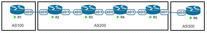
如下拓扑:
其中R2345内部启用OSPF,R2和R5建立BGP邻居关系,R1是AS100,R6是AS300。R1和R6的环回接口宣告进BGP
1
2
3
4
5
6
7
8
9
10
11
12
13
14
15
16
17
18
19
20
21
22
23
24
25
26
27
28
29
30
31
32
33
34
35
36
37
38
39
40
41
42
43
44
45
46
47
48
49
50
51
52
53
54
55
56
57
58
59
60
61
62
63
64
65
66
67
68
69
70
71
72
73
74
75
76
77
78
79
80
81
82
83
84
85
86
87
R1 interface Loopback0 ip address 1.1.1.1 255.255.255.255 ! interface Ethernet0/0 ip address 192.168.12.1 255.255.255.0 ! router bgp 100 bgp log-neighbor-changes network 1.1.1.1 mask 255.255.255.255 neighbor 192.168.12.2 remote-as 200 ========================================= R2 interface Loopback0 ip address 2.2.2.2 255.255.255.255 ip ospf 1 area 0 ! interface Ethernet0/0 ip address 192.168.12.2 255.255.255.0 ! interface Ethernet0/1 ip address 192.168.23.2 255.255.255.0 ip ospf 1 area 0 ! router bgp 200 bgp log-neighbor-changes neighbor 5.5.5.5 remote-as 200 neighbor 5.5.5.5 update-source Loopback0 neighbor 5.5.5.5 next-hop-self neighbor 192.168.12.1 remote-as 100 ========================================= R3 interface Loopback0 ip address 3.3.3.3 255.255.255.255 ip ospf 1 area 0 ! interface Ethernet0/0 ip address 192.168.23.3 255.255.255.0 ip ospf 1 area 0 ! interface Ethernet0/1 ip address 192.168.34.3 255.255.255.0 ip ospf 1 area 0 ===================================== R4 interface Loopback0 ip address 4.4.4.4 255.255.255.255 ip ospf 1 area 0 ! interface Ethernet0/0 ip address 192.168.34.4 255.255.255.0 ip ospf 1 area 0 ! interface Ethernet0/1 ip address 192.168.45.4 255.255.255.0 ip ospf 1 area 0 ==================================== R5 interface Loopback0 ip address 5.5.5.5 255.255.255.255 ip ospf 1 area 0 ! interface Ethernet0/0 ip address 192.168.45.5 255.255.255.0 ip ospf 1 area 0 ! interface Ethernet0/1 ip address 192.168.56.5 255.255.255.0 ! router bgp 200 bgp log-neighbor-changes neighbor 2.2.2.2 remote-as 200 neighbor 2.2.2.2 update-source Loopback0 neighbor 2.2.2.2 next-hop-self neighbor 192.168.56.6 remote-as 300 ========================================= R6 interface Loopback0 ip address 6.6.6.6 255.255.255.255 ! interface Ethernet0/0 ip address 192.168.56.6 255.255.255.0 ! router bgp 300 bgp log-neighbor-changes network 6.6.6.6 mask 255.255.255.255 neighbor 192.168.56.5 remote-as 200
通过上述配置,发现R1和R6可以互相学习lo0。但是无法互相访问。原因是路由黑洞,详情参考BGP部分课程。
可以通过MPLS来解决这个问题。
在AS200内的每个物理接口上加上一条mpls ip,然后稍等几秒
1
2
3
4
5
6
R6#ping 1.1.1.1 so 6.6.6.6 Type escape sequence to abort. Sending 5, 100-byte ICMP Echos to 1.1.1.1, timeout is 2 seconds: Packet sent with a source address of 6.6.6.6 !!!!! Success rate is 100 percent (5/5), round-trip min/avg/max = 1/1/1 ms
发现R3和R4依旧没有学习到任何的R1或者R6的路由条目
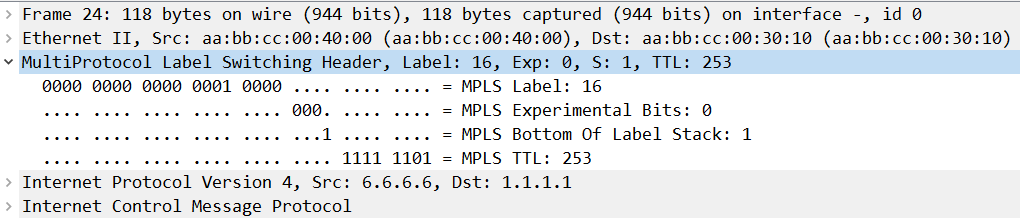
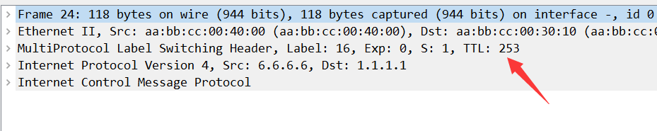
通过在R3和R4之间抓包,发现数据结构如下
MPLS原理 流量分析 由于MPLS标签始终从16开始分配,为了方便观察和实验,我们规定R2只能用200-299的标签,R3只能用300-399以此类推,这样就可以看到标签的传递的过程。但是真实网络中,没必要规定标签范围。
1
2
3
4
5
6
7
8
9
10
11
12
13
14
15
R2(config)#mpls label range 200 299 R2(config)#int e0/1 R2(config-if)#mpls ip =========================== R3(config)#mpls label range 300 399 R3(config)#int range e0/0 -1 R3(config-if-range)#mpls ip =========================== R4(config)#mpls label range 400 499 R4(config)#int range e0/0 -1 R4(config-if-range)#mpls ip =========================== R5(config)#mpls label range 500 599 R5(config)#int e0/0 R5(config-if)#mpls ip
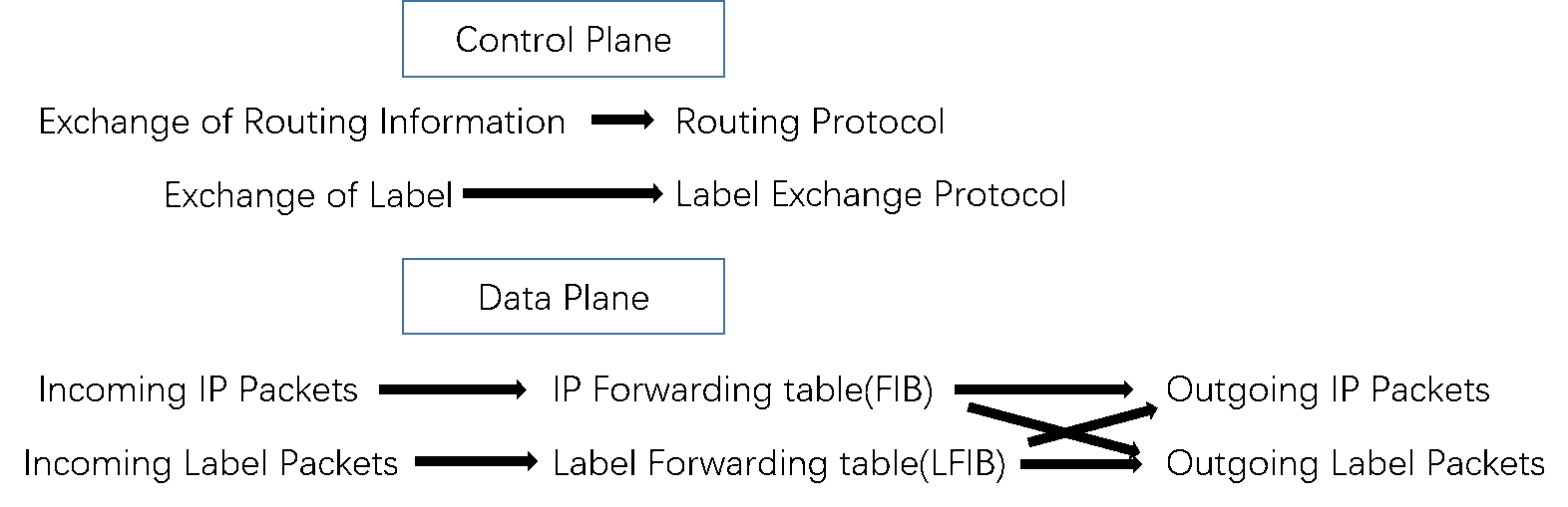
下面开始分析流量的走向。
如果路由器转发IP包,会查找cef表。show ip cef x.x.x.x
如果路由器转发标签包,会查找标签转发信息库。show mpls forward-table
从R1出发 ,产生了s-ip:1.1.1.1,d-ip:6.6.6.6的IP数据包,在Cisco设备中,路由器并不是直接查找路由表确定出接口的。Cisco设备有特快转发机制(可以理解为预缓存),查找CEF表,确定出接口。
1
2
3
R1#sh ip cef 6.6.6.6 6.6.6.6/32 nexthop 192.168.12.2 Ethernet0/0
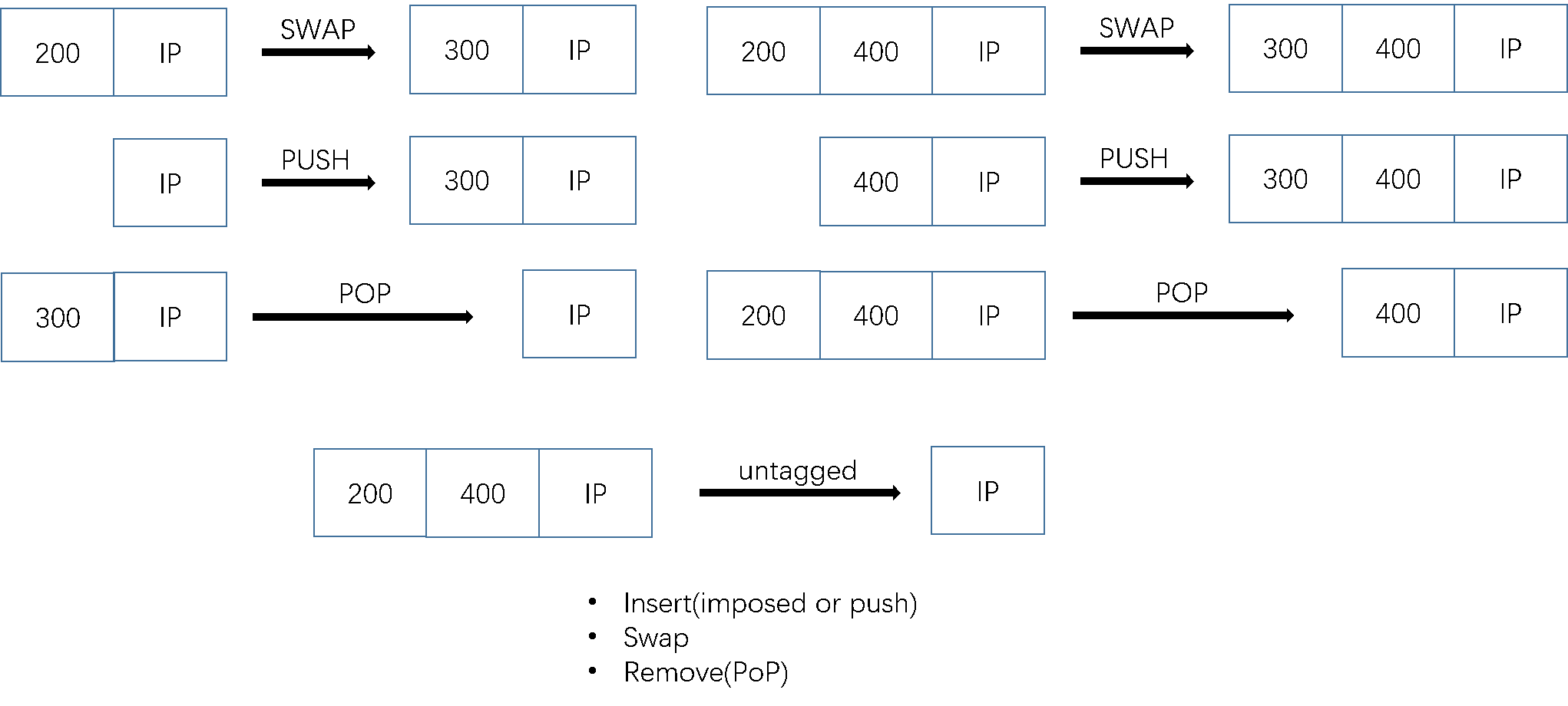
R2收到了R1发来的IP数据包 ,查找CEF表,在cef表中,发现这个条目已经被预先缓存加上标签302再从e0/1转发。这时候R2发出的已经是标签包了。
1
2
3
R2#sh ip cef 6.6.6.6 6.6.6.6/32 nexthop 192.168.23.3 Ethernet0/1 label 302-(local:200)
R3收到了R2发来的标签数据包 ,查找标签转发信息库,我们发现标签302对应标签402,所以数据中的标签就变成了402,然后从e0/1发出。
1
2
3
4
5
6
7
R3#sh mpls forwarding-table Local Outgoing Prefix Bytes Label Outgoing Next Hop Label Label or Tunnel Id Switched interface 300 Pop Label 2.2.2.2/32 1468 Et0/0 192.168.23.2 301 Pop Label 4.4.4.4/32 0 Et0/1 192.168.34.4 302 402 5.5.5.5/32 208 Et0/1 192.168.34.4 303 Pop Label 192.168.45.0/24 0 Et0/1 192.168.34.4
R4收到了R3的标签包 ,查找标签转发信息库,我们发现标签402对应操作是删除标签,所以数据中的标签就被删除,然后从e0/1发出。
1
2
3
4
5
6
7
R4#show mpls forwarding-table Local Outgoing Prefix Bytes Label Outgoing Next Hop Label Label or Tunnel Id Switched interface 400 300 2.2.2.2/32 285 Et0/0 192.168.34.3 401 Pop Label 3.3.3.3/32 0 Et0/0 192.168.34.3 402 Pop Label 5.5.5.5/32 1541 Et0/1 192.168.45.5 403 Pop Label 192.168.23.0/24 0 Et0/0 192.168.34.3
R5收到R4的IP包 ,查找CEF表,最终发给了目的地
1
2
3
R5#sh ip cef 6.6.6.6 6.6.6.6/32 nexthop 192.168.56.6 Ethernet0/1
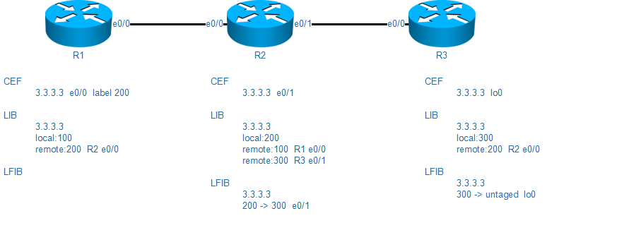
标签的产生 LDP(标签发现协议)这个协议随着MPLS启动
LDP启动
给路由表中每个条目都分配一个标签,不规定范围就从16开始,每个条目的标签称为本地标签
可以通过show mpls ldp binding查看本地标签
通过参与LDP的接口与直连路由器建立LDP邻居
可以通过show mpls ldp neighbor查看邻居
LDP从邻居那边学习对方给他的条目分配的本地标签,然后记为远程标签
可以通过show mpls ldp binding查看远程标签
通过IGP的下一跳判断最佳远程标签,然后结合CEF的出接口信息,产生LFIB(标签转发信息库)
可以通过show mpls forwarding-table查看标签转发信息库
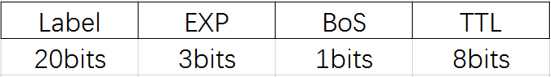
MPLS标签 标签结构
Label
标签数值(范围16-1048575)
0-15是保留标签,部分有特殊功能
可以人为指定范围
EXP
BoS
在有些应用下可能会有多层标签,BoS是1,就表示最底层的标签
TTL
在加上标签的时候,会将IPv4报头中的TTL复制过来
在去除标签的时候,会将标签中TTL复制到IPv4报头中
数据包的防环机制
标签的位置 在数据链路层与网络层之间
标签的处理动作
标签空间 LDP可以在同一台设备上给每个条目分配一个标签,这个称为基于平台的标签空间,会在LDP ID的后面用:0表示
LDP也可以基于接口来给每个条目分配不同的标签,会更加的安全
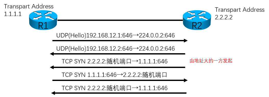
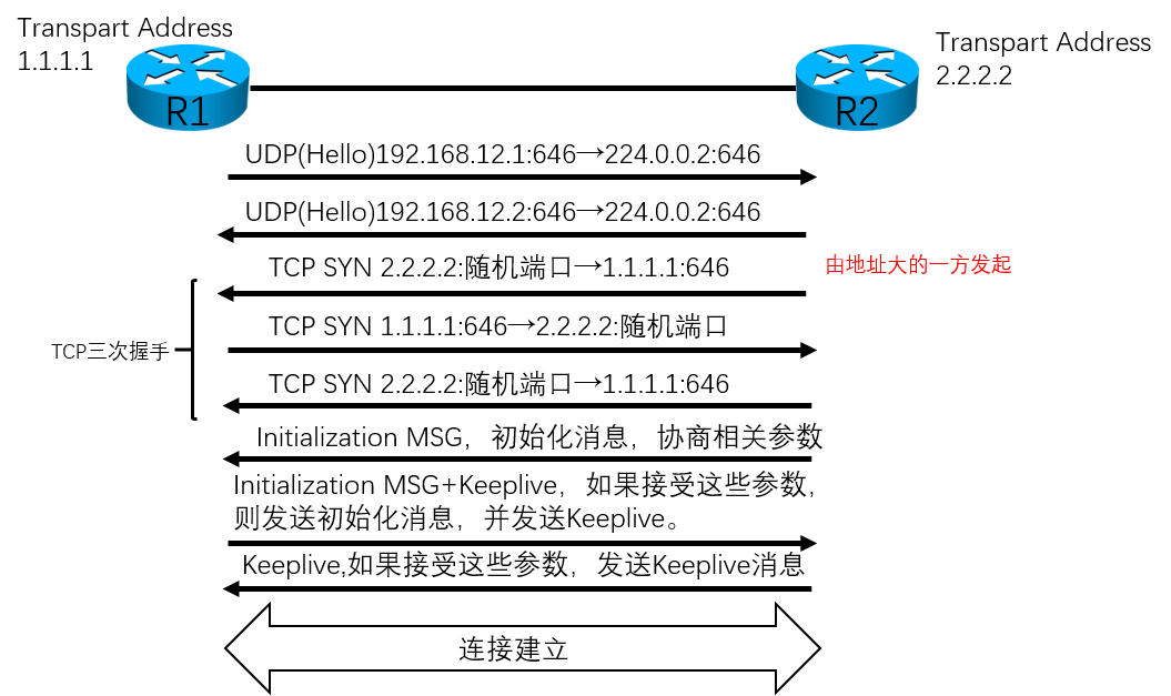
LDP详解 LDP邻居建立过程 邻居发现过程
从646端口发送udp的hello包
hello包的地址是224.0.0.2
会话建立的过程
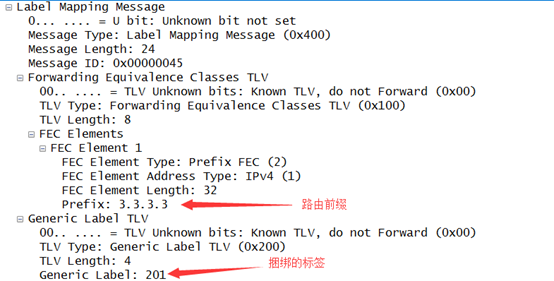
初始化消息中携带的路由前缀以及对应的捆绑标签
LDP各种计时器查看
1
2
3
4
5
6
7
8
9
10
11
12
13
14
15
16
17
R3#sh mpls ldp parameters LDP Feature Set Manager: State Initialized LDP features: Basic IP-over-MPLS TDP IGP-Sync Auto-Configuration TCP-MD5-Rollover Protocol version: 1 Session hold time: 180 sec; keep alive interval: 60 sec Discovery hello: holdtime: 15 sec; interval: 5 sec Discovery targeted hello: holdtime: 90 sec; interval: 10 sec Downstream on Demand max hop count: 255 LDP for targeted sessions LDP initial/maximum backoff: 15/120 sec LDP loop detection: off
如果R3不将loopback0通告进OSPF,可以看到R2依旧可以发现R3,但是无法建立tcp会话。
LDP的邻居发现和会话建立是不同的机制。
1
2
3
4
5
6
7
8
9
10
11
12
13
R2#sh mpls ldp nei Peer LDP Ident: 3.3.3.3:0 No TCP connection; Downstream Up time: 00:16:03 Addresses bound to peer LDP Ident: 192.168.23.3 192.168.34.3 3.3.3.3 R2#show mpls ldp discovery Local LDP Identifier: 2.2.2.2:0 Discovery Sources: Interfaces: Ethernet0/1 (ldp): xmit/recv LDP Id: 3.3.3.3:0; no route
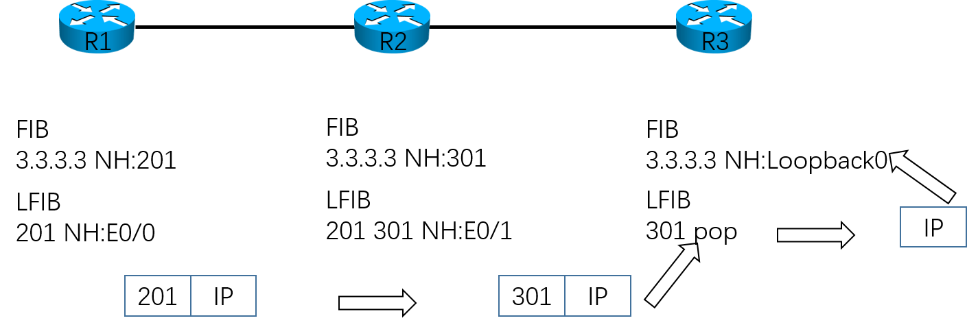
PHP次末跳弹出机制
在使用次末跳弹出之前,到达目的地的数据仍然是标签包,目的地需要先查找标签转发信息库,然后删除标签变成IP包,再次查找FIB表。出现两次查表,浪费性能。
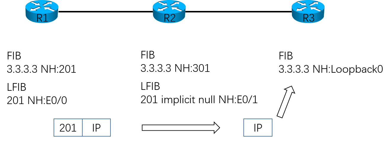
在使用了次末跳弹出机制之后,R3会产生一个空标签给R2,告诉R2我就是目的地,这样R2就会在发给R3之前将标签删除。
LDP在给本地直连条目分配标签的时候,会分配隐含空标签(标签数值为3),这样倒数第二跳就会知道下一跳就是目的地了,然后提前删除标签。
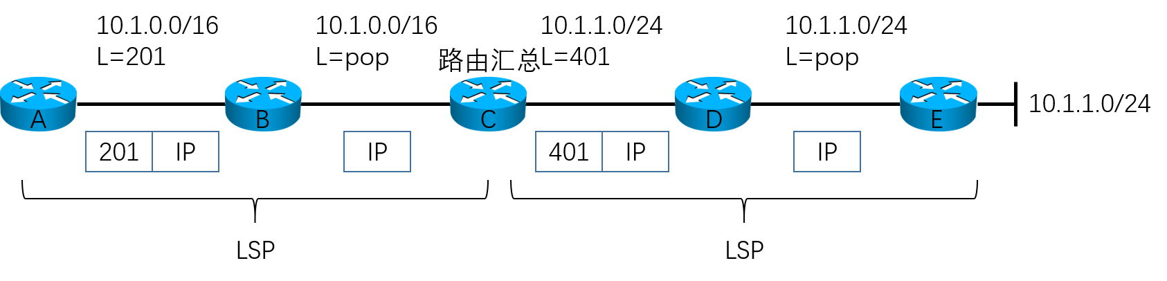
路由汇总对MPLS的影响
路由汇总本质上是抑制明细条目,然后本地产生一条新的汇总路由,并且更新出去
所以汇总路由的目的地就是执行汇总的这台路由器,导致路由条目在汇总路由器前一跳被弹出标签。
如果是在MPLS VPN或者BGP路由黑洞中,这种提前弹出标签的行为,会直接丢包。